THEORY: To design an engine that is annular in configuration and specifically designed to run on water as a fuel. An engine that would be inversely proportional to the load or an engine that becomes part of the fuselage. An engine designed to operate throughout the atmosphere and in space, because an engine that burns water does not require carbonation or air intake.
DATE of ORIGIN: November, 2002.
DESCRIPTION: These engines are ring-shaped, flexible and have only one spinning part.  There is no crank shaft, no bearings, no oil based lubricant, no valves, no fuel pump or air intake. The engine consists of a ring (or Crank) that slides in the center of a “C” shaped base (or Block). The crank has any number of kinetic pistons that bottom out at the end of their stroke and transfer their kinetic energy into the crank ring, forcing the crank to spin in the direction of the piston compression.
 These engines take advantage of quantum geometry and use the Laws of Physics. Just like in Newton’s Cradle where the kinetic energy is transferred from the moving ball, through the stationary balls and into the last ball causing it to move.
There are two primary uses for these engines. The first is to put them into large concrete bunkers with hydro generators on top of them.

The second use is that these engines are designed to power the Galaxycraft. The Galaxycraft is an annular or circular flying aircraft for atmospheric and space flight. They are to be used as a flying atmospheric platform therefore a new kind of aircraft.
1. The Annular Kinetic engine
These engines are designed to be very simplistic and do not resemble anything currently being used. The engine is designed to be incorporated into a circular or annular wing. These engines are also designed to be added together and be shut down independently from each other. It would be possible to have as many as sixteen engines in one Galaxycraft.
The engines operate continuously without stopping for months at a time. The crank spins inside the block, in a layer of high pressure steam where there is little friction or wear on them. Only the crank rings and piston springs would develop fatigue and would have to be maintained. In a multiple engine design, any one engine can be shut down while the others continue running.

Above are four engines stacked, the individual engines are “clutched” together such that one of them could be shut down for repairs while the remaining engines continue to run.
2. Simplicity by Design
These Engines are designed to be built of composites rather than metal.  They are made of carbon fiber and plastics with metal cylinder sleeves, springs and cylinder heads. They are to be light, flexible and spin very fast. It is this very design that holds them together. No matter how fast the crank spins, it will never be able to spin out of the block.
The engines have only one moving or spinning part and that is the crank. The crank can have any number of pistons but the point here is to have a lot of them. If the crank was twenty meters or even fifty meters in diameter, it could have hundreds of pistons. All firing at different times at multiple sites around the block.
This is a two-stroke engine, a firing stroke and a return stroke. The pistons return to firing position by spring action. The stroke is only a couple of centimeters long, because it is a kinetic engine using the Laws of Inertia and Laws of Motion.  The piston bottoms out, or hits the end of the cylinder at the bottom of the stroke and transfers its kinetic energy into the crank.
3. There is no air intake
 The fuel injection is automatic, as the injection port is always open. The back-pressure in the fuel/lubrication zone forces fuel into the cylinder chamber at all times. The size of the fuel injection port is to be only a few millimeters so that the fuel can enter, but the explosion in the cylinder head will not escape. This occurs in part because of the back pressure in the fuel/lubrication zone and because a quick and sudden explosion that expands the volume of air will force down the piston before it can escape through the small fuel port.
The “firing” takes place through the same fuel injection port as it continues to rotate and move past the antenna. The antenna is constantly on. As the open port moves past the antenna, 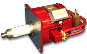 it sends the signal into the cylinder head, splitting the water molecule and igniting the fuel under pressure.
There are to be many firing positions around the block such that by the time it takes the piston to return to the top of its stroke, it is ready to fire again. A computer could set the firing order to suit the need with multiple antennae firing at the same time or independently in rapid order.

After firing, the piston spring is compressed and the mass of the piston is suddenly stopped against the bottom of the cylinder. This transfers the kinetic energy into the crank, which in turn spins the crank forward. There are short, wedge-shaped slots or grooves ground into the side walls of the cylinder for relieving the back pressure when the piston returns to the top of its stroke.
4. There are no moving valves
Again, this engine has been designed to be as simple as possible. That means there are no working or mechanical valves that could break down.  This is the reason for the constantly open intake port and the reason for the grooves in the side walls of the cylinder. There is also an exhaust port that is always open at the bottom of the cylinder that exhausts the air pressure in the cylinder chamber behind the piston.
The fuel tank is fastened to the inside of the crank ring, such that centrifugal force runs the fuel down a line and forces it into the lining between the crank and the block. This is the fuel/lubrication zone, pressurizing the water and lubricating the area between the block and the crank.

5. There are no bearings
The block has a pair of steel rings to keep the fuel/lubricant from leaking out at the mouth of the block. The distance between the block and the crank is only a few millimeters and the fuel/lubricant is drawn into this area by  centrifugal force. This is because the fuel tank is not as far from the center as is the block. The fuel(water) heats up and is vaporized as the crank spins inside the block.
This highly pressurized and vaporized fuel also acts as the lubricant between the block and the crank. The faster the crank turns, the higher the lubricant pressure increases, making the engine self-lubricating. The crank is the only spinning part.

6. A fuel that can be found everywhere
These engines are designed to run on water, as they are designed for space travel. Water (and ice) is the only unrefined fuel available in space.  It is the water that becomes pressurized and vaporized.
The annular kinetic engine will have lots of energy to produce the electromagnetic energy that is required, as well as having residual energy to be  effective to carry the load. The H2O provides both the “air” and the “fuel” needed to operate in space. As well, water provides the opportunity to find more fuel in space, in the form of ice.
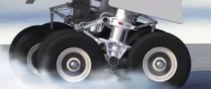
This engine below has thousands of moving parts, and the weight is disproportionate to the HP output. They are here to show the difference in complexity in both their operation and construction. 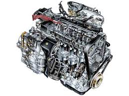 These types of engines (internal combustion) and (jet propulsion) are too heavy to achieve the same horsepower -to-weight ratio that the Annular Kinetic engine can achieve.
Please see: Carbon Free Fuel, The Galaxycraft and The Cosmos.
Hope you Enjoy.

 Then to induce an uneven influence to cause the rotor to turn. Trying to harness the power of magnets.
 There are over five hundred magnets with a combined force of over 2500 pounds of force. The idea is to use this force to create a rotation force.
 Of course, for every action there is an equal and opposite action. So in theory the motor will never work. But an imagination is a powerful driver of innovation. The idea is to balance the rotor in the magnetic field of the
  stator. Once that is achieved the next step is to induce an imbalance in the rotational direction causing the rotor to turn.
 the background you can see the two halves of the stator with the top half floating above the bottom half. This motor is made of three basic materials, paper, glue and 5 lbs rare earth magnets. The stand is made of wood and brass.

 The boundary layer is that layer of water that is next to the hull as the hull tries to move forward through the water. This layer is often only twelve centimeters thick but it creates drag on the length of the hull.
 Others have demonstrated that bubbles ejected under the hull reduces drag along the boundary layer.
 they reach from the keel to the water line. Each gill like vent extends out into the water about ten centimeters. As the ship moves forward the gill vents scrape away the boundary layer reducing the friction.
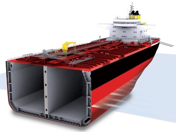 The exhaust tube inside is twice as big as the surface area of the boundary layer on the outside, reducing the pressure by half.
  The exhaust tube starts at the bow of the ship looking like a crescent moon and ends at the stern of the ship looking like a circle.
 Now instead of a rudder and single propeller at the stern. The single propeller and rudder are removed and there is installed two propellers, one in each exhaust tube. These propellers will create a vacuum in the exhaust tubes thus sucking the ship forward. The exhaust tubes would also be used to steer the ship with one going faster than the other or by reversing one of them. Thereby steering the ship without inducing drag.


 around us is an energy source that is not only consistent, but powerful.
 applied all around the world, even when there are no valleys to flood. With different scales of track and turbines for different applications or sizes of rivers.
 much faster than the speed of the turbine and most fish will treat the turbine like rapids and just swim over them. As well screens or guards could be employed.
 turbine blades, they are fitted with passive vanes that swing open with the back pressure of the return stroke. Then close under the pressure of the power stroke.
 As can be seen above. The environmental impact is very low with three simple steps to install and all three can be reversed if necessary. First start by preparing the surface of the river bottom by removing the mud and debris. Then lay down a layer of gravel and finally lay down precast concrete sections installed with rail tracks.


 A Frames.


